RETRO GAMES™
Bitfunx OSSC HW V1.8 Open Source Scan Converter HDMI Adapter for PS2 SEGA Saturn Nintendo64 Gamecube MD Retro Game Consoles
Bitfunx OSSC HW V1.8 Open Source Scan Converter HDMI Adapter for PS2 SEGA Saturn Nintendo64 Gamecube MD Retro Game Consoles
Couldn't load pickup availability
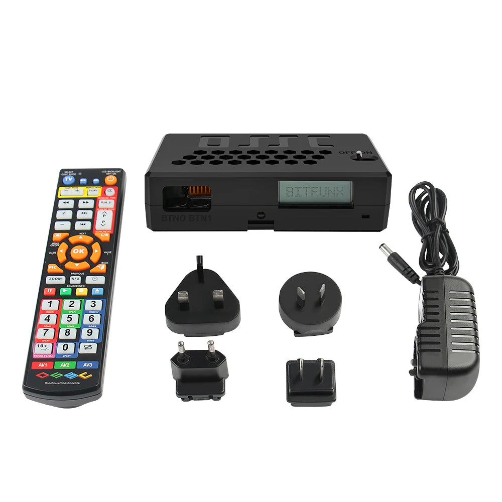
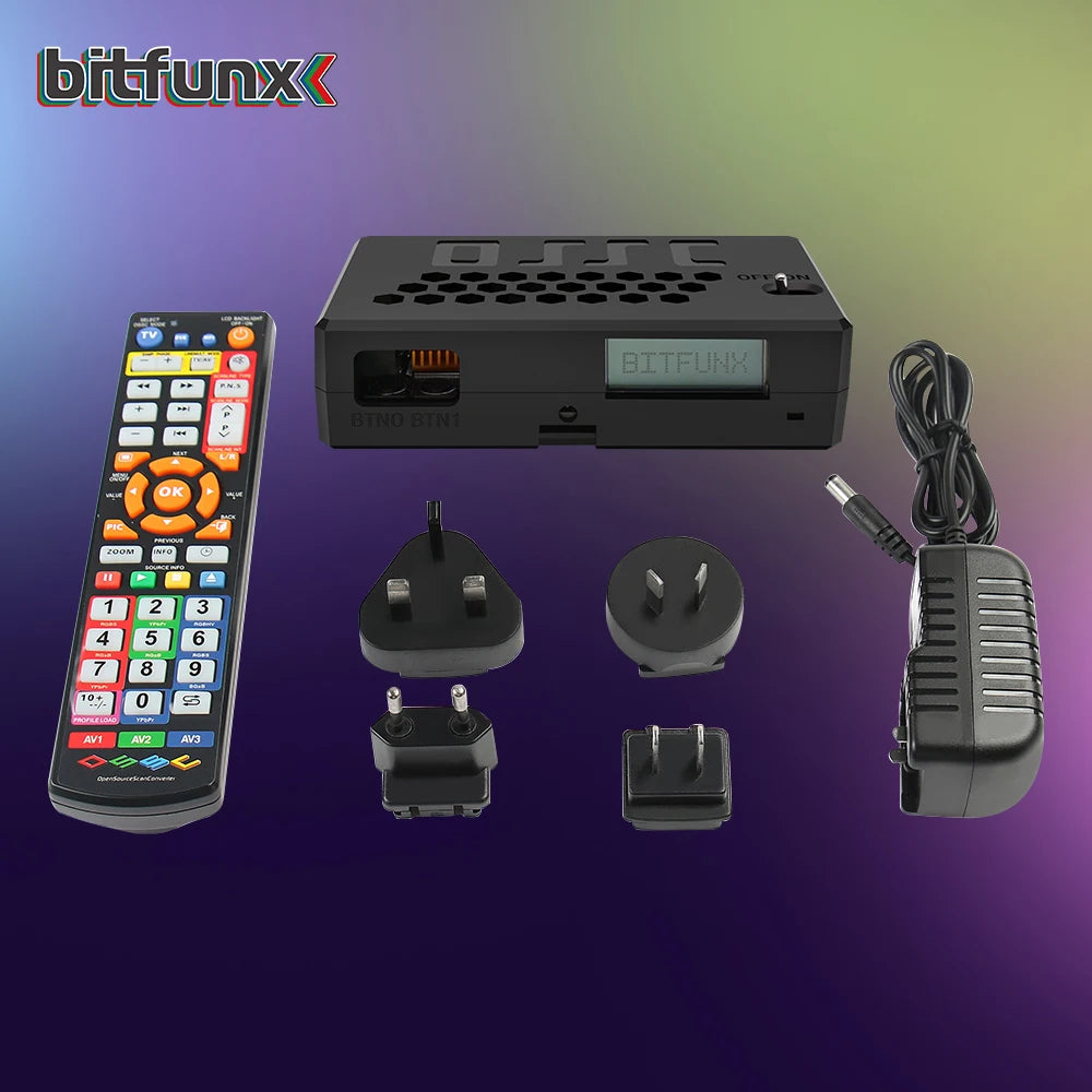
Bitfunx OSSC HW V1.8 – Open Source Scan Converter HDMI Adapter for Retro Game Consoles
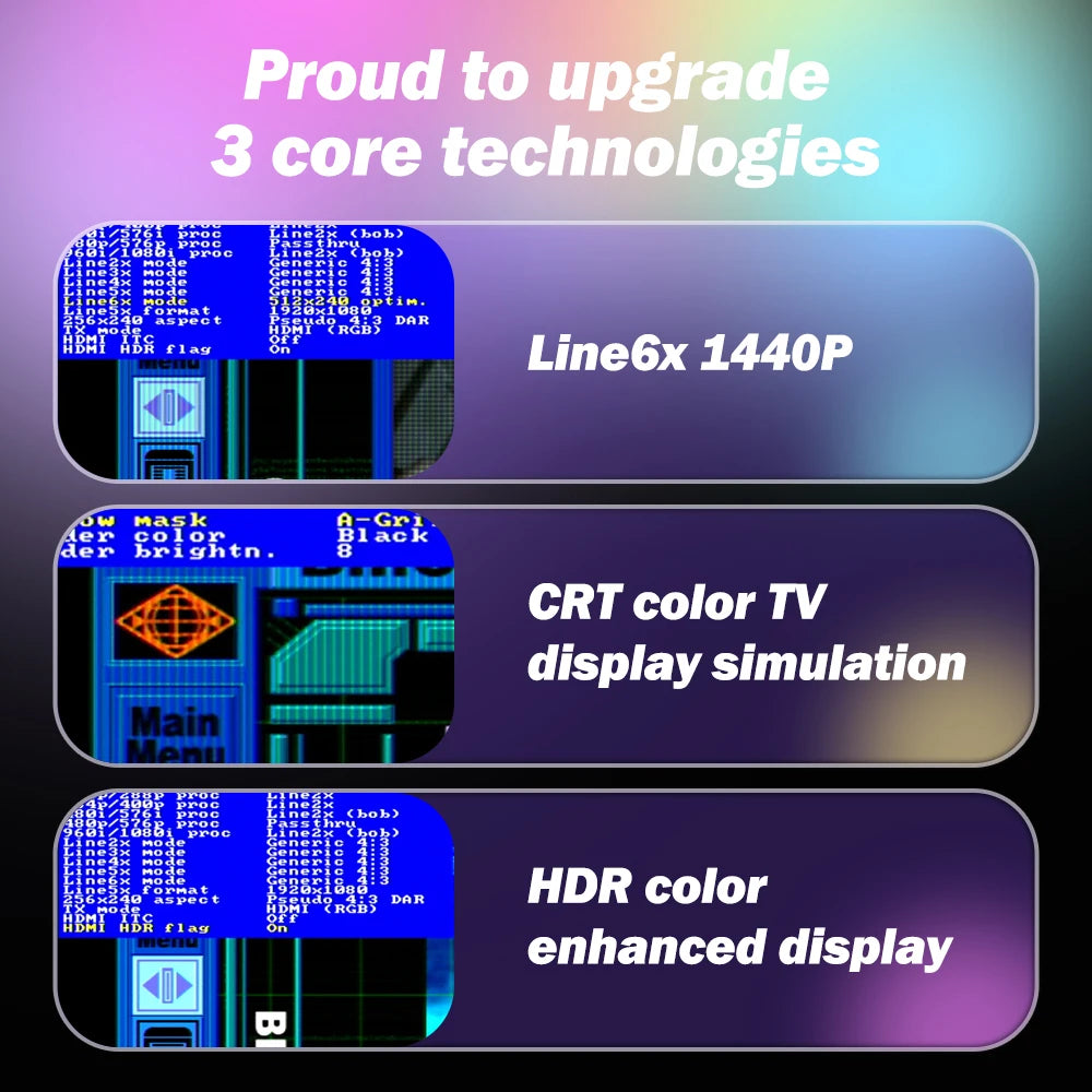
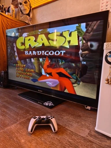
Take your retro gaming to the next level with the Bitfunx OSSC HW V1.8 Open Source Scan Converter, designed to upscale classic console signals into crisp HDMI output for modern TVs. Whether you’re playing on a PS2, SEGA Saturn, Dreamcast, Mega Drive, Nintendo 64, or GameCube, this advanced converter ensures lag-free, high-quality visuals for the ultimate retro experience.
Key Features
-
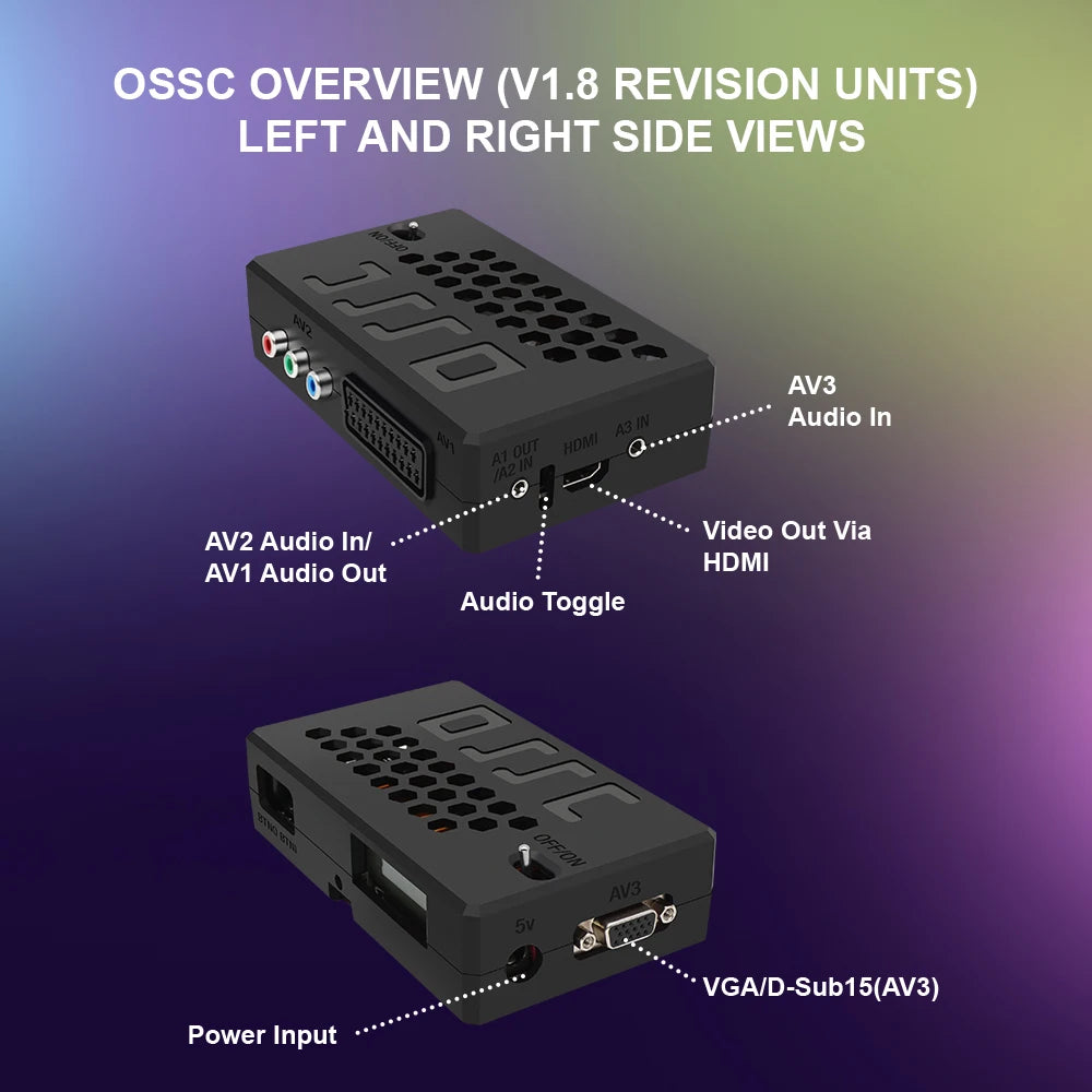
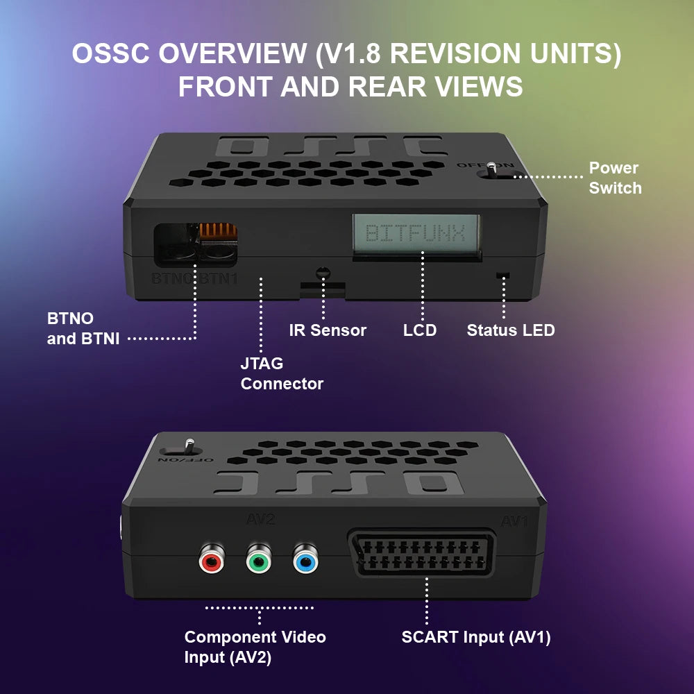
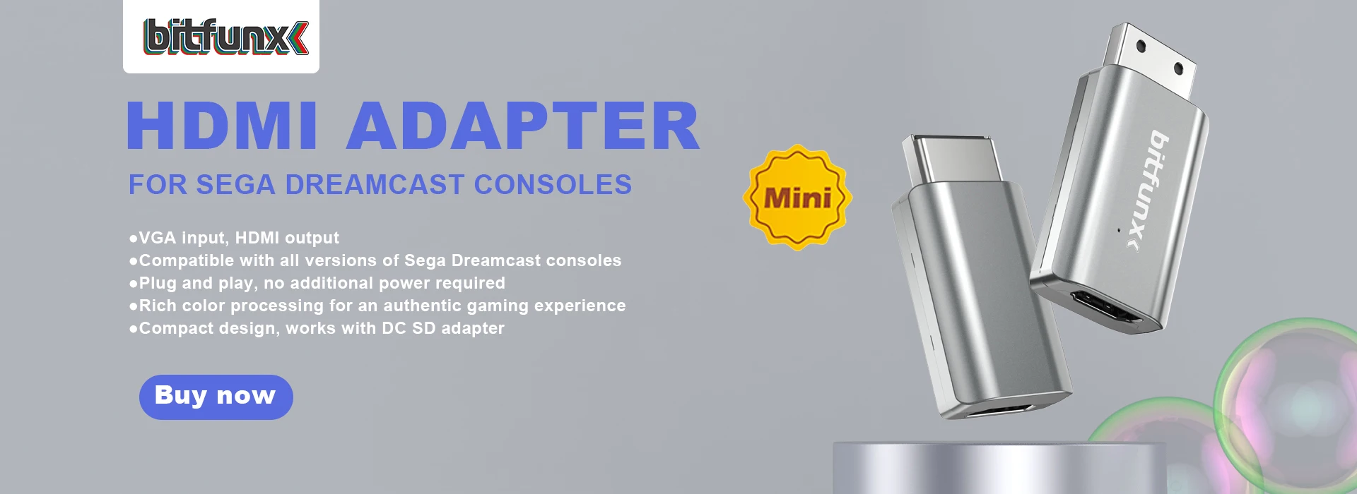
Supports Multiple Input Formats – Compatible with VGA, Component, and SCART signals, making it versatile for a wide range of classic consoles. Perfect for SEGA Mega Drive, Saturn, Dreamcast, Nintendo 64, GameCube, PlayStation 2, and many more retro systems.
-
High-Quality HDMI Output – Converts analog signals into sharp digital HDMI, allowing you to enjoy classic games on modern HDTVs and monitors without sacrificing quality.
-
Lag-Free Gaming – Unlike traditional scalers that introduce input delay, the OSSC provides zero-lag signal conversion, ensuring an authentic, responsive retro gaming experience.
-
Upgradeable Firmware – With firmware that can be updated via MicroSD card, you can keep your OSSC up to date with the latest features and improvements.
-
Remote Control Included – Fine-tune your settings effortlessly using the included remote control, adjusting options like aspect ratio, scanlines, and output resolution to create your preferred gaming setup.
-
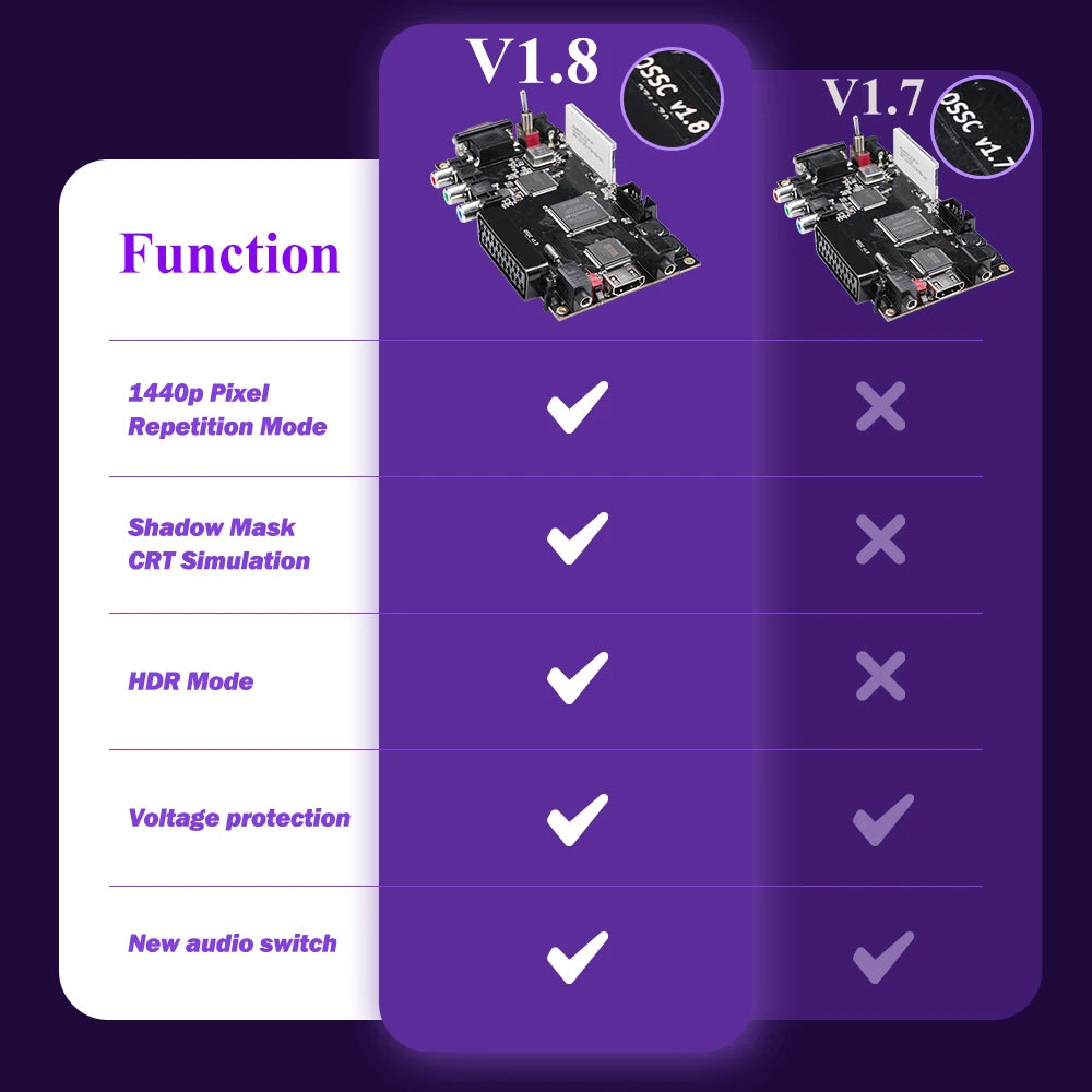
Powerful Hardware – The HW V1.8 model ensures improved stability and compatibility compared to earlier versions, delivering consistent performance for demanding retro gamers.
-
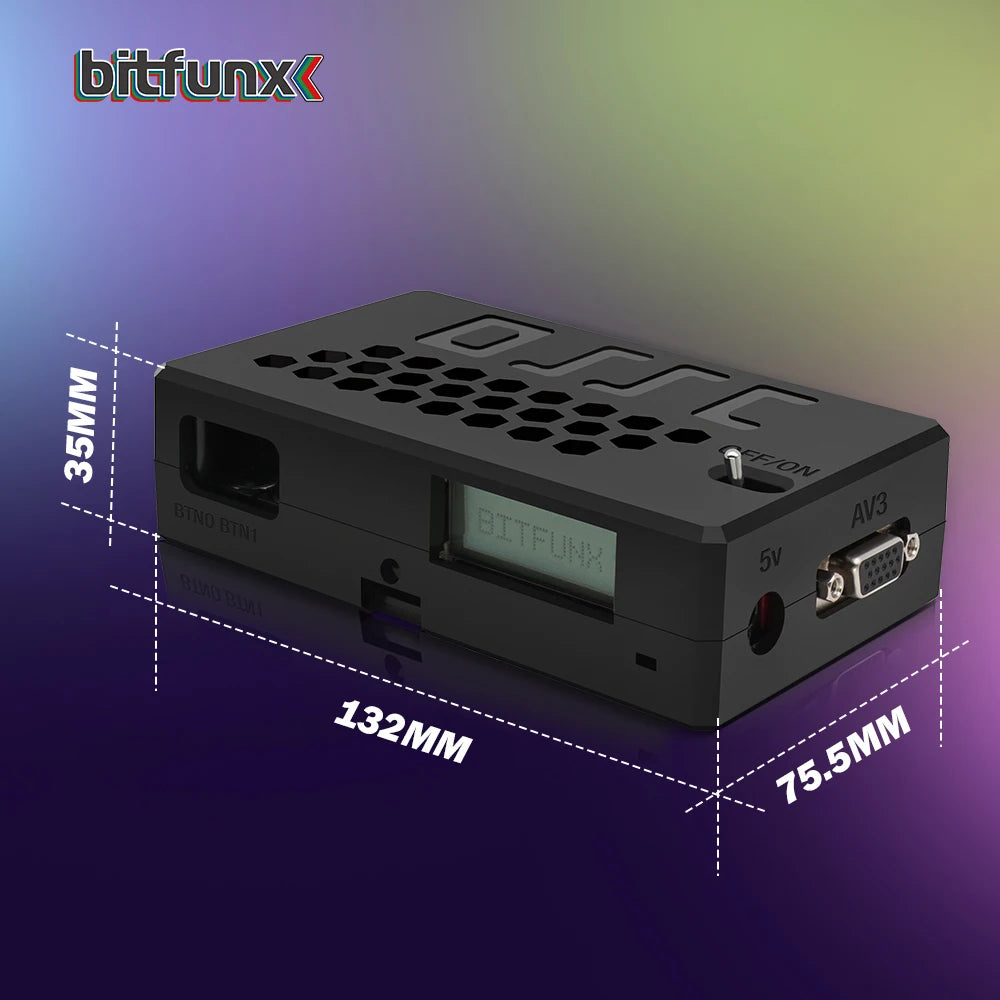
Plug-and-Play Simplicity – Easy to set up and operate, with clear connectivity for quick installation. Simply connect your retro console, plug in the OSSC, and start playing.


Why Choose the Bitfunx OSSC HW V1.8?
Modern TVs often struggle with the low-resolution outputs of retro consoles, leading to poor image quality or input lag. The Bitfunx OSSC eliminates these issues by upscaling classic signals in real time, producing vivid, clean graphics that stay true to the original design while looking stunning on modern displays.
For collectors, streamers, and enthusiasts, this device is a must-have. It preserves the authentic feel of retro gameplay while enhancing visuals for today’s screens, making it ideal for tournaments, retro streams, or personal collections.
Benefits
-
Enjoy retro consoles on modern HDTVs with crystal-clear HDMI output.
-
No input lag, ensuring competitive and authentic gameplay.
-
Compatible with a wide range of systems, including SEGA, PlayStation, and Nintendo classics.
-
Customizable settings via remote control for the perfect display.
-
Upgradeable firmware ensures long-term use and improvements.
Upgrade Your Retro Setup
Bring your classic consoles back to life in stunning HD with the Bitfunx OSSC HW V1.8 Scan Converter. Perfect for gamers who value both authenticity and modern performance, it’s the ultimate tool for transforming your retro library into a sleek, modern gaming experience.

Reviews - Why Customers Love RETRO GAMES™
-
Absolutely Perfect for Retro Lovers ⭐ ⭐ ⭐ ⭐ ⭐
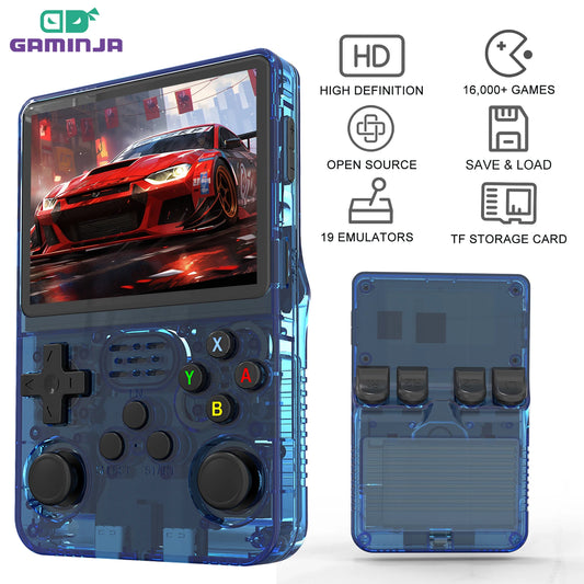
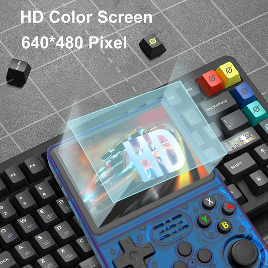
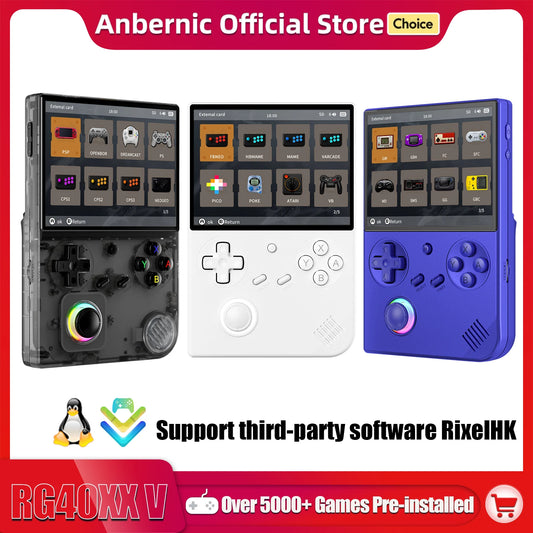
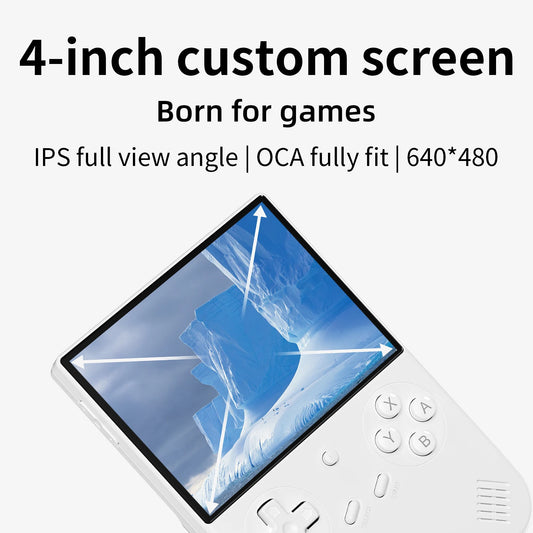
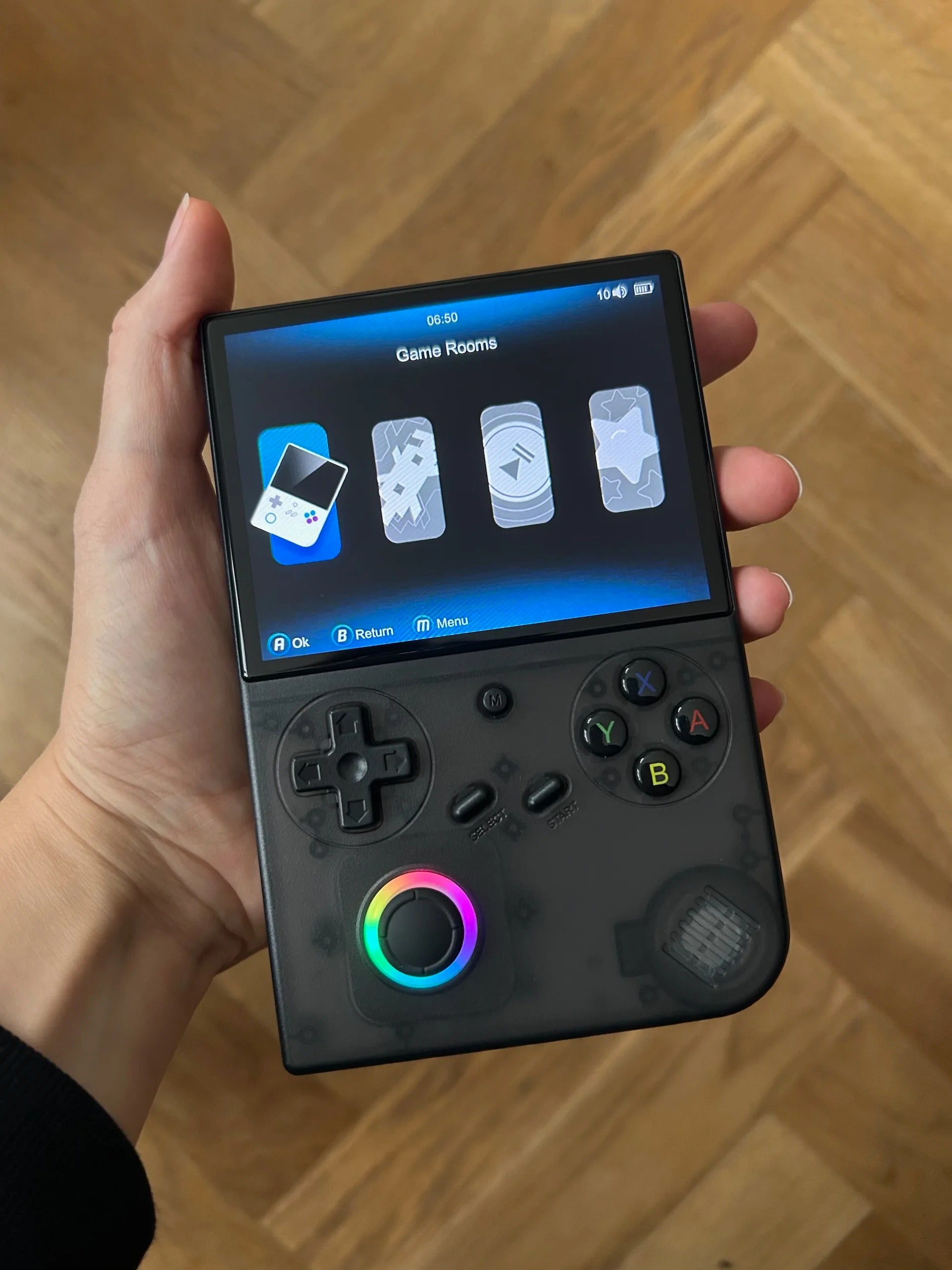
Anbernic RG40XXV Retro Handheld Game Console
The screen is crystal clear, and it runs every classic I grew up with flawlessly. Love that it connects easily to my TV for multiplayer fun!
— Ethan M., Austin, TX -
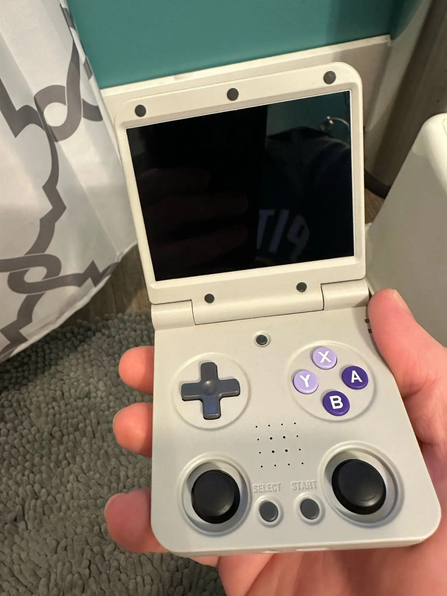
So Addictive and Compact ⭐ ⭐ ⭐ ⭐ ⭐
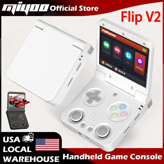
Miyoo Flip V2 Handheld Console
Feels like my childhood in my pocket! The dual analog sticks make it awesome for newer-style games too.
— Sofia L., Toronto, Canada -
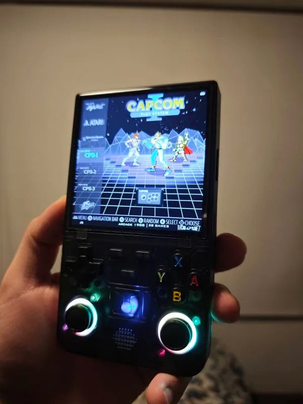
Pocket Powerhouse of Nostalgia ⭐ ⭐ ⭐ ⭐ ⭐
R36MAX Retro Handheld Game Console
This little console packs serious punch — smooth gameplay and tons of classics preloaded. The included carrying case makes it perfect for travel.
— Liam R., Manchester, UK -
Retro Gaming Meets Modern Design ⭐ ⭐ ⭐ ⭐ ⭐
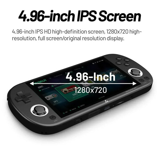
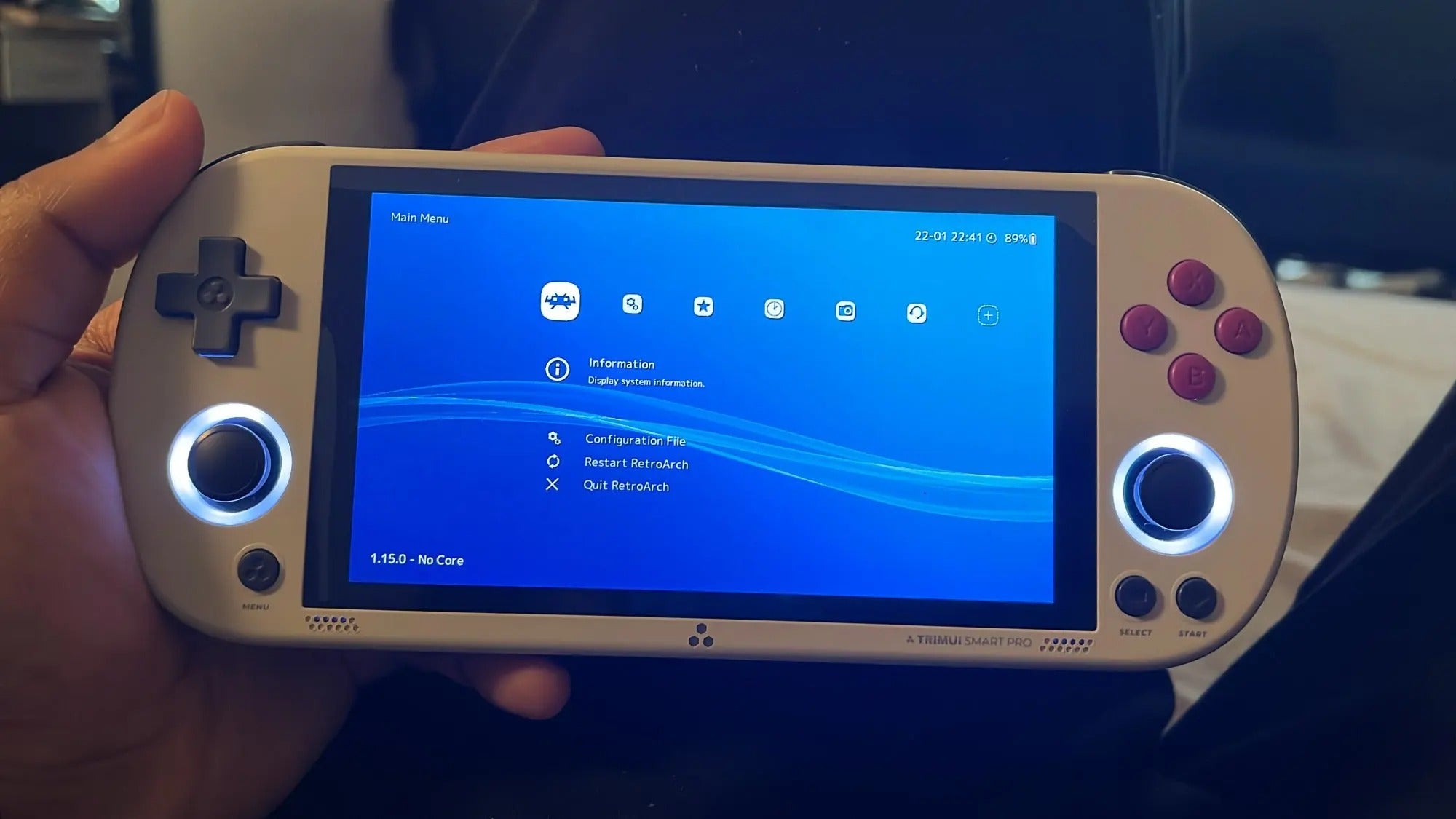
Trimui Smart Pro Handheld Console
The RGB lighting and sleek feel make this console stand out. Runs everything super smooth and looks amazing on the shelf.
— Carlos J., Miami, FL -
Ultimate Plug & Play Retro Setup ⭐ ⭐ ⭐ ⭐ ⭐
Retro Game Console with Dual Wireless Joysticks
Thousands of classics ready to play in seconds, and the wireless controllers make it a blast with friends. Incredible value for what it delivers.
— Ryan D., Los Angeles, CA -
Perfect Way to Organize My Game Collection ⭐ ⭐ ⭐ ⭐ ⭐
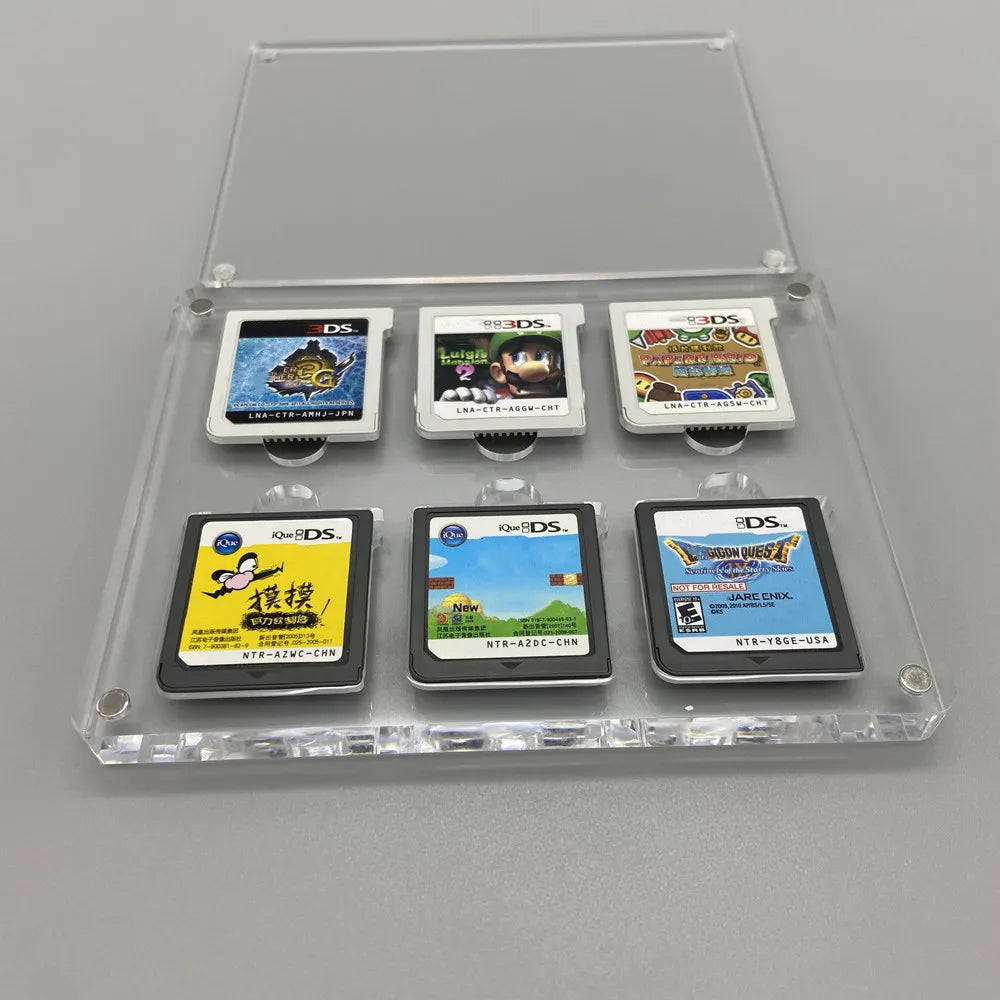
Acrylic Magnetic Game Storage Box
The magnetic lid feels premium and keeps my DS cartridges spotless. It’s both functional and looks great on my gaming desk!
— Hannah T., Melbourne, Australia -
Classic Sega Vibes Restored! ⭐ ⭐ ⭐ ⭐ ⭐
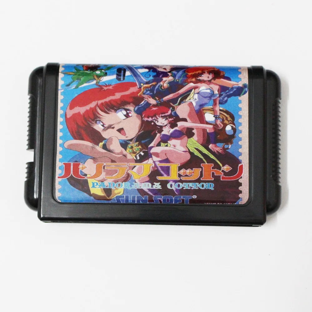
Panorama Cotton 16-Bit MD Game Card
Runs flawlessly on my Genesis and brings back that authentic 16-bit magic. The artwork on the cartridge is stunning, too.
— Mika S., Tokyo, Japan -
Brought My Game Boy Pocket Back to Life ⭐ ⭐ ⭐ ⭐ ⭐
New GBP IPS LCD Screen Replacement
Super bright and easy to install — my old Game Boy looks brand new again. Couldn’t believe the color clarity until I saw it!
— Noah P., Berlin, Germany


Best Selling Handheld Retro Consoles
-
R36S Open Source K36 Handheld Game Console 3.5Inch IPS Screen Built in 16000 Games Supports online doubles For PS1/PSP/DC
Vendor:RETRO GAMES™Regular price From CHF 37.49Regular priceUnit price perCHF 0.00Sale price From CHF 37.49R36S Open Source K36 Handheld Game Console 3.5Inch IPS Screen Built in 16000 Games Supports online doubles For PS1/PSP/DC
Regular price From CHF 37.49Regular priceUnit price perCHF 0.00Sale price From CHF 37.49R36S Open Source K36 Handheld Game Console 3.5Inch IPS Screen Built in 16000 Games Supports online doubles For PS1/PSP/DC
Regular price From CHF 37.49Regular priceUnit price perCHF 0.00Sale price From CHF 37.49 -
ANBERNIC RG 40XXV 64 Bit Linux Retro Handheld Game Console 4.0'' IPS Screen Supports 5G WiFi Bluetooth HD-Out RG40XXV With APP
Vendor:RETRO GAMES™Regular price From CHF 127.36Regular priceUnit price perCHF 0.00Sale price From CHF 127.36ANBERNIC RG 40XXV 64 Bit Linux Retro Handheld Game Console 4.0'' IPS Screen Supports 5G WiFi Bluetooth HD-Out RG40XXV With APP
Regular price From CHF 127.36Regular priceUnit price perCHF 0.00Sale price From CHF 127.36ANBERNIC RG 40XXV 64 Bit Linux Retro Handheld Game Console 4.0'' IPS Screen Supports 5G WiFi Bluetooth HD-Out RG40XXV With APP
Regular price From CHF 127.36Regular priceUnit price perCHF 0.00Sale price From CHF 127.36 -
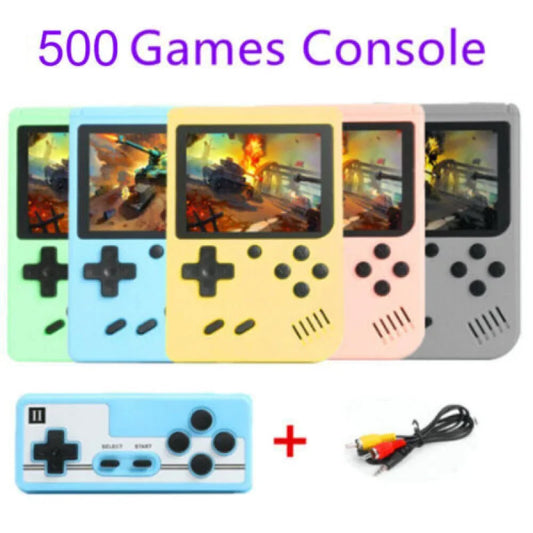
Built-in 500+ Classic games 5 inch arcade retro Console games console for Game boy Emulator TV Video Game Handheld Game Player
Vendor:RETRO GAMES™Regular price From CHF 9.59Regular priceUnit price perCHF 0.00Sale price From CHF 9.59Built-in 500+ Classic games 5 inch arcade retro Console games console for Game boy Emulator TV Video Game Handheld Game Player
Regular price From CHF 9.59Regular priceUnit price perCHF 0.00Sale price From CHF 9.59Built-in 500+ Classic games 5 inch arcade retro Console games console for Game boy Emulator TV Video Game Handheld Game Player
Regular price From CHF 9.59Regular priceUnit price perCHF 0.00Sale price From CHF 9.59 -
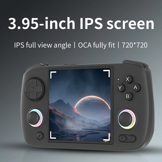
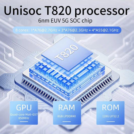
ANBERNIC RG Cubexx Retro Handheld Game Console 3.95" IPS 720*720 Screen Linux 64bit Support WiFi Bluetooth Streaming Video Games
Vendor:RETRO GAMES™Regular price From CHF 139.93Regular priceUnit price perCHF 0.00Sale price From CHF 139.93ANBERNIC RG Cubexx Retro Handheld Game Console 3.95" IPS 720*720 Screen Linux 64bit Support WiFi Bluetooth Streaming Video Games
Regular price From CHF 139.93Regular priceUnit price perCHF 0.00Sale price From CHF 139.93ANBERNIC RG Cubexx Retro Handheld Game Console 3.95" IPS 720*720 Screen Linux 64bit Support WiFi Bluetooth Streaming Video Games
Regular price From CHF 139.93Regular priceUnit price perCHF 0.00Sale price From CHF 139.93 -
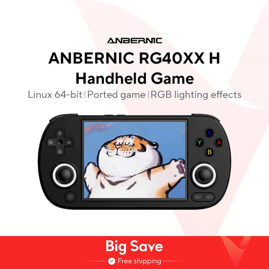
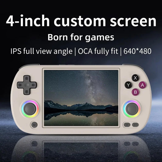
ANBERNIC RG40XX H 64 Bit Linux Retro Handheld Game Console 4.0'' IPS Screen Supports 5G WiFi Bluetooth HDMI-TV Output RG40XXH
Vendor:RETRO GAMES™Regular price CHF 83.79Regular priceUnit price perCHF 0.00Sale price CHF 83.79 -
ANBERNIC RG 406V Handheld Game Console 4" IPS Multi-touch Screen Android13 RG406V Retro Video Games Support 1080p DP FOTA Update
Vendor:RETRO GAMES™Regular price From CHF 192.94Regular priceUnit price perCHF 0.00Sale price From CHF 192.94ANBERNIC RG 406V Handheld Game Console 4" IPS Multi-touch Screen Android13 RG406V Retro Video Games Support 1080p DP FOTA Update
Regular price From CHF 192.94Regular priceUnit price perCHF 0.00Sale price From CHF 192.94ANBERNIC RG 406V Handheld Game Console 4" IPS Multi-touch Screen Android13 RG406V Retro Video Games Support 1080p DP FOTA Update
Regular price From CHF 192.94Regular priceUnit price perCHF 0.00Sale price From CHF 192.94 -
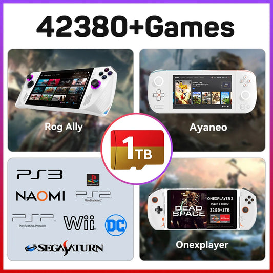
512G Game Card for ROG Ally/Ayaneo/OnexPlayer/Handheld Game Consoles/PC for PS3/PS2/SS/PS1/PSP/DC/MAME 50+Emulators&38200+Games
Vendor:RETRO GAMES™Regular price From CHF 125.56Regular priceUnit price perCHF 0.00Sale price From CHF 125.56512G Game Card for ROG Ally/Ayaneo/OnexPlayer/Handheld Game Consoles/PC for PS3/PS2/SS/PS1/PSP/DC/MAME 50+Emulators&38200+Games
Regular price From CHF 125.56Regular priceUnit price perCHF 0.00Sale price From CHF 125.56512G Game Card for ROG Ally/Ayaneo/OnexPlayer/Handheld Game Consoles/PC for PS3/PS2/SS/PS1/PSP/DC/MAME 50+Emulators&38200+Games
Regular price From CHF 125.56Regular priceUnit price perCHF 0.00Sale price From CHF 125.56 -
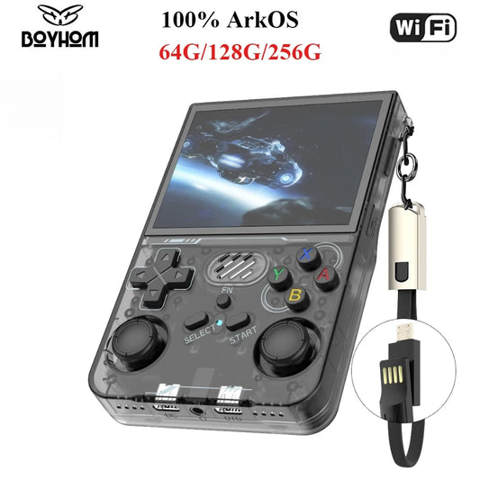
100% ArKOS R36XX Retro Handheld Game Console Linux System 3.5 Inch IPS Screen 64/128GB/256GB Game Player R36S updated version
Vendor:RETRO GAMES™Regular price From CHF 57.00Regular priceUnit price perCHF 0.00Sale price From CHF 57.00100% ArKOS R36XX Retro Handheld Game Console Linux System 3.5 Inch IPS Screen 64/128GB/256GB Game Player R36S updated version
Regular price From CHF 57.00Regular priceUnit price perCHF 0.00Sale price From CHF 57.00100% ArKOS R36XX Retro Handheld Game Console Linux System 3.5 Inch IPS Screen 64/128GB/256GB Game Player R36S updated version
Regular price From CHF 57.00Regular priceUnit price perCHF 0.00Sale price From CHF 57.00 -
ANBERNIC RG35XX H Handheld Game Console Linux 3.5 inch IPS Screen H700 Retro Video Games Player 3300mAh 64G 5528 Classic Games
Vendor:RETRO GAMES™Regular price CHF 81.65Regular priceUnit price perCHF 0.00Sale price CHF 81.65 -
ANBERNIC RG40XX H 64 Bit Linux Retro Handheld Game Console 4.0'' IPS Screen Supports 5G WiFi Bluetooth HDMI-TV Output RG40XXH
Vendor:RETRO GAMES™Regular price CHF 86.65Regular priceUnit price perCHF 0.00Sale price CHF 86.65 -
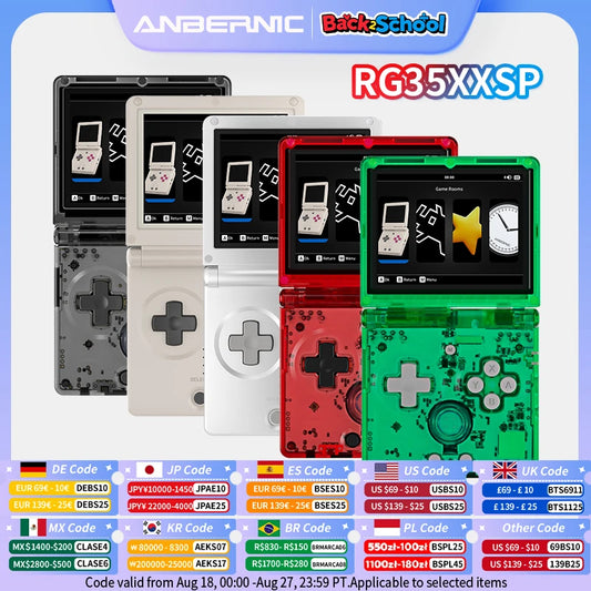
ANBERNIC RG35XXSP Flip Handheld Game Console 3.5'' IPS Screen Linux 64bit WiFi Bluetooth Retro Video Gaming Console 64G 5K Games
Vendor:RETRO GAMES™Regular price From CHF 79.21Regular priceUnit price perCHF 0.00Sale price From CHF 79.21ANBERNIC RG35XXSP Flip Handheld Game Console 3.5'' IPS Screen Linux 64bit WiFi Bluetooth Retro Video Gaming Console 64G 5K Games
Regular price From CHF 79.21Regular priceUnit price perCHF 0.00Sale price From CHF 79.21ANBERNIC RG35XXSP Flip Handheld Game Console 3.5'' IPS Screen Linux 64bit WiFi Bluetooth Retro Video Gaming Console 64G 5K Games
Regular price From CHF 79.21Regular priceUnit price perCHF 0.00Sale price From CHF 79.21 -
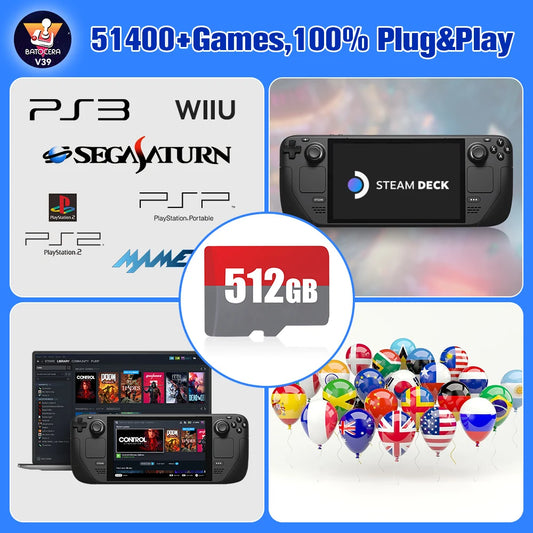
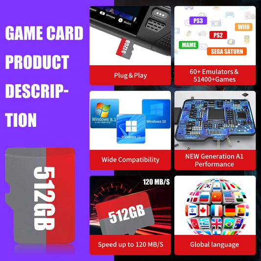
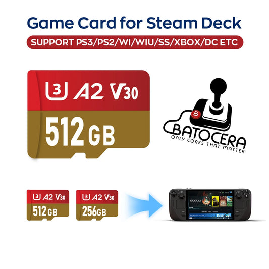
Batocera TF/Game Card for Steam Deck/Windows PC/MAC/Handheld Game Console for PS3/PS2/SS/PS1/PSP/DC/MAME 70+Emulators&51400+Game
Vendor:RETRO GAMES™Regular price From CHF 40.86Regular priceUnit price perCHF 0.00Sale price From CHF 40.86Batocera TF/Game Card for Steam Deck/Windows PC/MAC/Handheld Game Console for PS3/PS2/SS/PS1/PSP/DC/MAME 70+Emulators&51400+Game
Regular price From CHF 40.86Regular priceUnit price perCHF 0.00Sale price From CHF 40.86Batocera TF/Game Card for Steam Deck/Windows PC/MAC/Handheld Game Console for PS3/PS2/SS/PS1/PSP/DC/MAME 70+Emulators&51400+Game
Regular price From CHF 40.86Regular priceUnit price perCHF 0.00Sale price From CHF 40.86 -
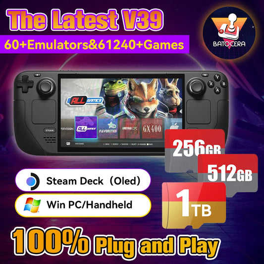
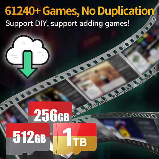
Batocera TF/Game Card for Steam Deck/Windows PC/MAC/Handheld Game Console for PS3/PS2/SS/PS1/PSP/DC/MAME 70+Emulators&61240+Game
Vendor:RETRO GAMES™Regular price From CHF 85.96Regular priceUnit price perCHF 0.00Sale price From CHF 85.96Batocera TF/Game Card for Steam Deck/Windows PC/MAC/Handheld Game Console for PS3/PS2/SS/PS1/PSP/DC/MAME 70+Emulators&61240+Game
Regular price From CHF 85.96Regular priceUnit price perCHF 0.00Sale price From CHF 85.96Batocera TF/Game Card for Steam Deck/Windows PC/MAC/Handheld Game Console for PS3/PS2/SS/PS1/PSP/DC/MAME 70+Emulators&61240+Game
Regular price From CHF 85.96Regular priceUnit price perCHF 0.00Sale price From CHF 85.96 -
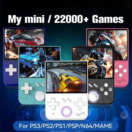
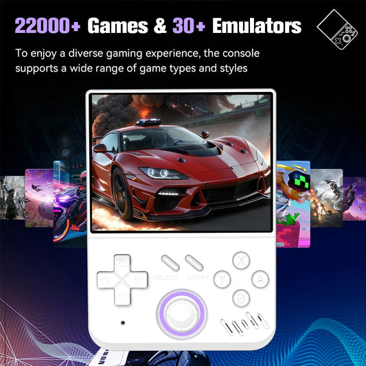
128GB My mini Retro Handheld Game Console 3.5-inch IPS Screen Linux System with 22000+Games for PS3/PS2/PS1/PSP/N64 for Gifts
Vendor:RETRO GAMES™Regular price From CHF 65.98Regular priceUnit price perCHF 0.00Sale price From CHF 65.98128GB My mini Retro Handheld Game Console 3.5-inch IPS Screen Linux System with 22000+Games for PS3/PS2/PS1/PSP/N64 for Gifts
Regular price From CHF 65.98Regular priceUnit price perCHF 0.00Sale price From CHF 65.98128GB My mini Retro Handheld Game Console 3.5-inch IPS Screen Linux System with 22000+Games for PS3/PS2/PS1/PSP/N64 for Gifts
Regular price From CHF 65.98Regular priceUnit price perCHF 0.00Sale price From CHF 65.98 -
Batocera TF/Game Card for Steam Deck/Windows/MAC/Handheld Game Console for PS3/PS2/SS/PS1/PSP/DC/MAME 30+Emulators&15000+Games
Vendor:RETRO GAMES™Regular price From CHF 55.15Regular priceUnit price perCHF 0.00Sale price From CHF 55.15Batocera TF/Game Card for Steam Deck/Windows/MAC/Handheld Game Console for PS3/PS2/SS/PS1/PSP/DC/MAME 30+Emulators&15000+Games
Regular price From CHF 55.15Regular priceUnit price perCHF 0.00Sale price From CHF 55.15Batocera TF/Game Card for Steam Deck/Windows/MAC/Handheld Game Console for PS3/PS2/SS/PS1/PSP/DC/MAME 30+Emulators&15000+Games
Regular price From CHF 55.15Regular priceUnit price perCHF 0.00Sale price From CHF 55.15 -
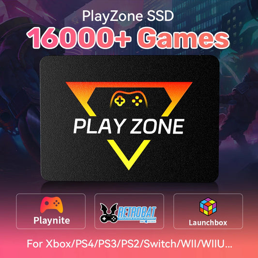
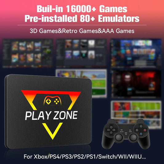
PlayZone 1TB External Emulator Game SSD Built-in 16000 Retro&AAA Games Portable Game Hard Drive For Xbox/Switch/PS4/PS3/NGC/WII
Vendor:RETRO GAMES™Regular price From CHF 118.00Regular priceUnit price perCHF 0.00Sale price From CHF 118.00PlayZone 1TB External Emulator Game SSD Built-in 16000 Retro&AAA Games Portable Game Hard Drive For Xbox/Switch/PS4/PS3/NGC/WII
Regular price From CHF 118.00Regular priceUnit price perCHF 0.00Sale price From CHF 118.00PlayZone 1TB External Emulator Game SSD Built-in 16000 Retro&AAA Games Portable Game Hard Drive For Xbox/Switch/PS4/PS3/NGC/WII
Regular price From CHF 118.00Regular priceUnit price perCHF 0.00Sale price From CHF 118.00 -
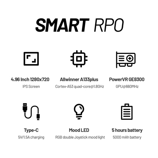
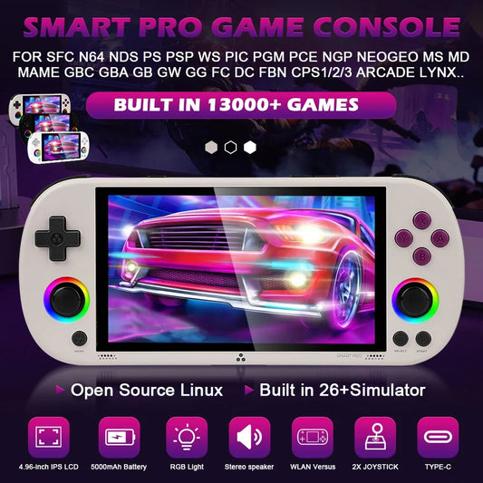
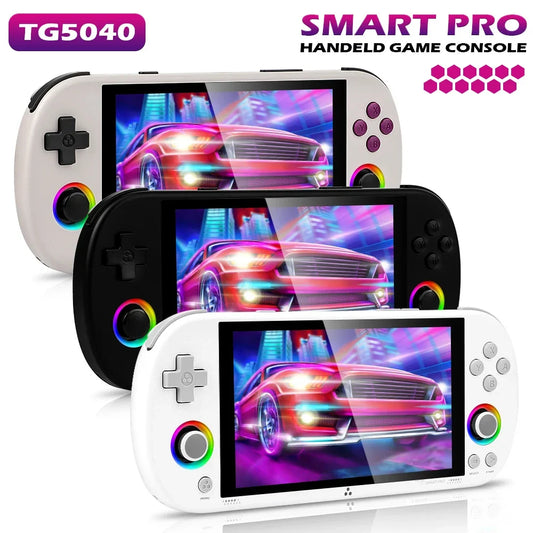
Trimui Smart Pro Handheld Game Console 4.96''IPS Screen Linux System Joystick RGB Lighting Smartpro Retro Video Game Player Gift
Vendor:RETRO GAMES™Regular price From CHF 124.19Regular priceUnit price perCHF 0.00Sale price From CHF 124.19Trimui Smart Pro Handheld Game Console 4.96''IPS Screen Linux System Joystick RGB Lighting Smartpro Retro Video Game Player Gift
Regular price From CHF 124.19Regular priceUnit price perCHF 0.00Sale price From CHF 124.19Trimui Smart Pro Handheld Game Console 4.96''IPS Screen Linux System Joystick RGB Lighting Smartpro Retro Video Game Player Gift
Regular price From CHF 124.19Regular priceUnit price perCHF 0.00Sale price From CHF 124.19 -
64G 128G 256G Portable Handheld Video Game Console 4.96'' IPS Screen Joystick RGB Lighting Smart Pro Retro Handheld Game Player
Vendor:RETRO GAMES™Regular price From CHF 123.54Regular priceUnit price perCHF 0.00Sale price From CHF 123.5464G 128G 256G Portable Handheld Video Game Console 4.96'' IPS Screen Joystick RGB Lighting Smart Pro Retro Handheld Game Player
Regular price From CHF 123.54Regular priceUnit price perCHF 0.00Sale price From CHF 123.5464G 128G 256G Portable Handheld Video Game Console 4.96'' IPS Screen Joystick RGB Lighting Smart Pro Retro Handheld Game Player
Regular price From CHF 123.54Regular priceUnit price perCHF 0.00Sale price From CHF 123.54 -
TRIMUI Smart Pro Handheld Game Players 4.96'' IPS Screen Portable Consoles Linux System Emulator Console Retro Video Game PS1
Vendor:RETRO GAMES™Regular price From CHF 85.58Regular priceUnit price perCHF 0.00Sale price From CHF 85.58TRIMUI Smart Pro Handheld Game Players 4.96'' IPS Screen Portable Consoles Linux System Emulator Console Retro Video Game PS1
Regular price From CHF 85.58Regular priceUnit price perCHF 0.00Sale price From CHF 85.58TRIMUI Smart Pro Handheld Game Players 4.96'' IPS Screen Portable Consoles Linux System Emulator Console Retro Video Game PS1
Regular price From CHF 85.58Regular priceUnit price perCHF 0.00Sale price From CHF 85.58 -
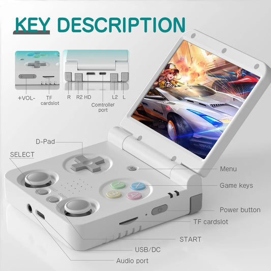
MIYOO Flip V2 Handheld Game Console 3.5Inch Childhood Classic Portable Retro Video Games Consoles Dual Analog Sticks Storage Bag
Vendor:RETRO GAMES™Regular price From CHF 82.60Regular priceUnit price perCHF 0.00Sale price From CHF 82.60MIYOO Flip V2 Handheld Game Console 3.5Inch Childhood Classic Portable Retro Video Games Consoles Dual Analog Sticks Storage Bag
Regular price From CHF 82.60Regular priceUnit price perCHF 0.00Sale price From CHF 82.60MIYOO Flip V2 Handheld Game Console 3.5Inch Childhood Classic Portable Retro Video Games Consoles Dual Analog Sticks Storage Bag
Regular price From CHF 82.60Regular priceUnit price perCHF 0.00Sale price From CHF 82.60